Ohlins + the MK60 kit arrives
I got my kit from Alex this week. It came surprisingly quick.
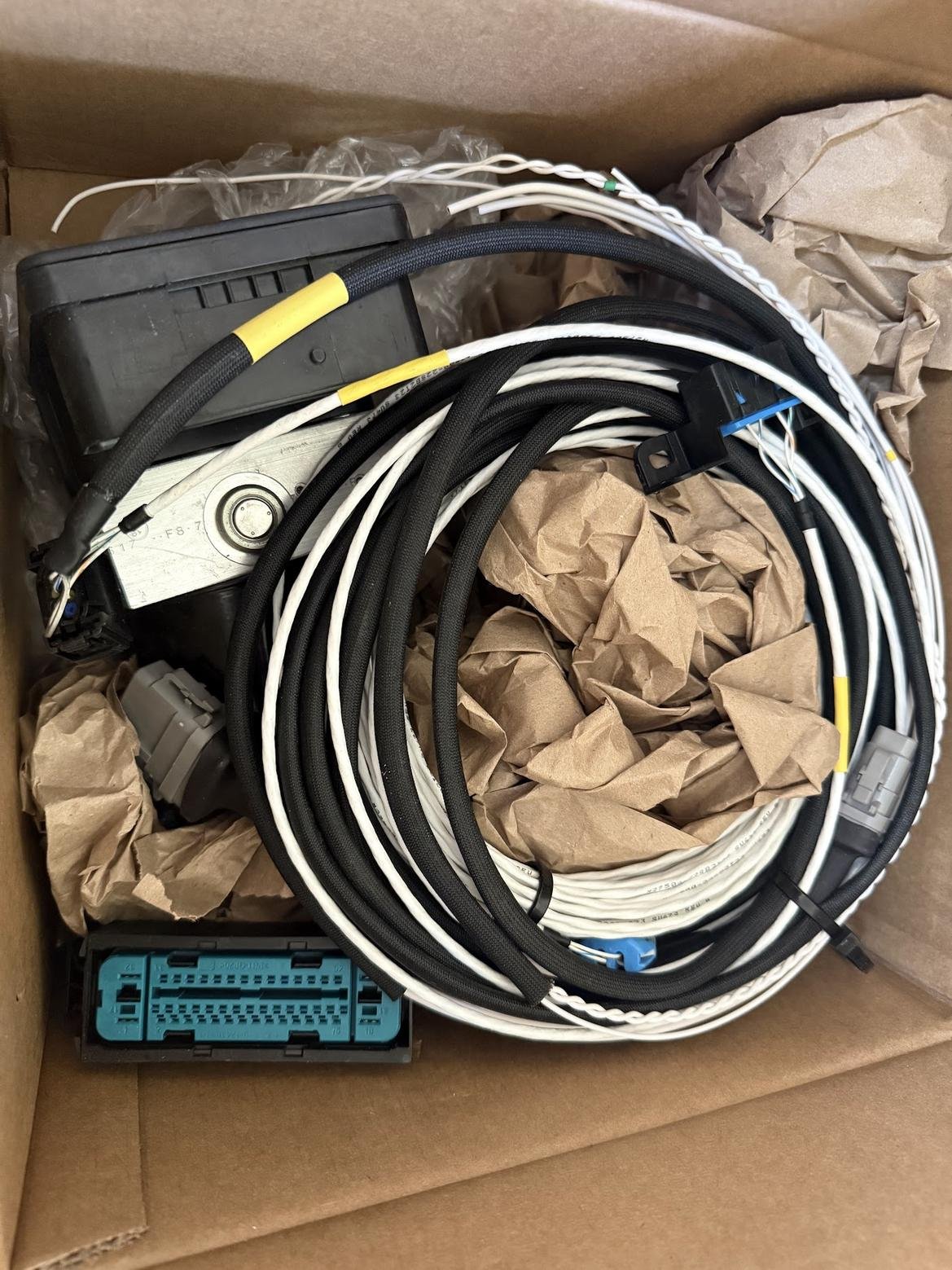
- Mk60e1 ABS unit
- ABS harness
- Sensor converter box to use voltage style corvette hubs
- Yaw sensor
- Wheel speed sensor harness.
The ABS harness has connections I need to chase down where to pick them up.
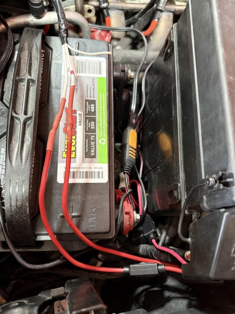
These two sound like I can run directly to the battery
- Red Band – Needs to be connected to 12v power through a fuse. Recommend a 30A fuse. Some users have gotten away with a 20A fuse, but OEM was 30A so that’s what I use.
- Orange Band – Same as the red banded wire. Needs its own 20-30A fuse. 30A recommended.
I assume this can be pickup up somewhere in the fuse box under the hood.
- Yellow Band – Needs to be connected to switched (key on) 12v power through a 5A fuse. This needs to be switched power, or the ABS unit will drain your battery when the car is off.
I think the C5 brake switch is positive when closed. I’ve heard that there are additional poles on the factory switch that might be used for the ground on press. Might be another version.
- Blue Band – This is the brake pedal/light switch signal. This tells the ABS module when the brake pedal is depressed and ABS should be enabled. This needs to be connected to ground when the brake pedal is pressed and an open circuit when not pressed. This is backwards from most cars (most cars are ground when not pressed and open circuit when pressed). Check your existing brake switch output and if it does exhibit the above behavior, you lucked out and you can just splice into the OEM brake pedal switch. If not, don’t fret; there are quite a few ways to do this, below are a few of the most common –
- Add an additional brake pedal switch. Using normally closed switch like one side of the the Painless 80176 and connect using the normally closed part of the switch. Connect to ground on one pin and the Blue Band wire of the ABS harness on the other.
- Add a brake pressure switch. Add this inline to one of the brake lines from the master cylinder to the ABS module. One pin should connect to ground and the other to the Blue Band wire of the ABS harness.
- Using a standard automotive relay to convert the signal from the OEM brake signal to the signal required by the MK60.
- Connect Pin 87 to Chassis Ground.
- Connect Pin 86 to OEM Brake light switch ‘hot when pressed’ wire
- Connect Pin 85 to Chassis Ground.
- Connect Pin 30 to the Blue Band wire of the ABS harness
- Connect a Zener Diode between Pin 86 and Pin 85 of the relay with the Band end at pin 86 to protect the switch from back EMF when power is removed
I assume you can just add a console MIL instead of trying to wire into the instrument cluster.
- Green Band – Connect to the positive side of the fault light (MIL). This is a 12v signal so ensure you’re using a 12v rated light
- Black Band – Connect to the negative side of the fault light (MIL)
I had already made a drill template, which is over on the facebook group (which you should join if you are doing this) There is also a happy cactus garage discord that you should probably join. They sell a mk60 sensor converter box, which I’m not using. However the community there is the right one to answer questions.
https://www.facebook.com/groups/807702710448164/permalink/1368785214339908
There is a helpful 3d model of the ABS out there as well
https://www.etsy.com/listing/1722585445/mk60e1-abs-reference-model?ref=yr_purchases
Last weekend I took off the fender and did a little planning with the model
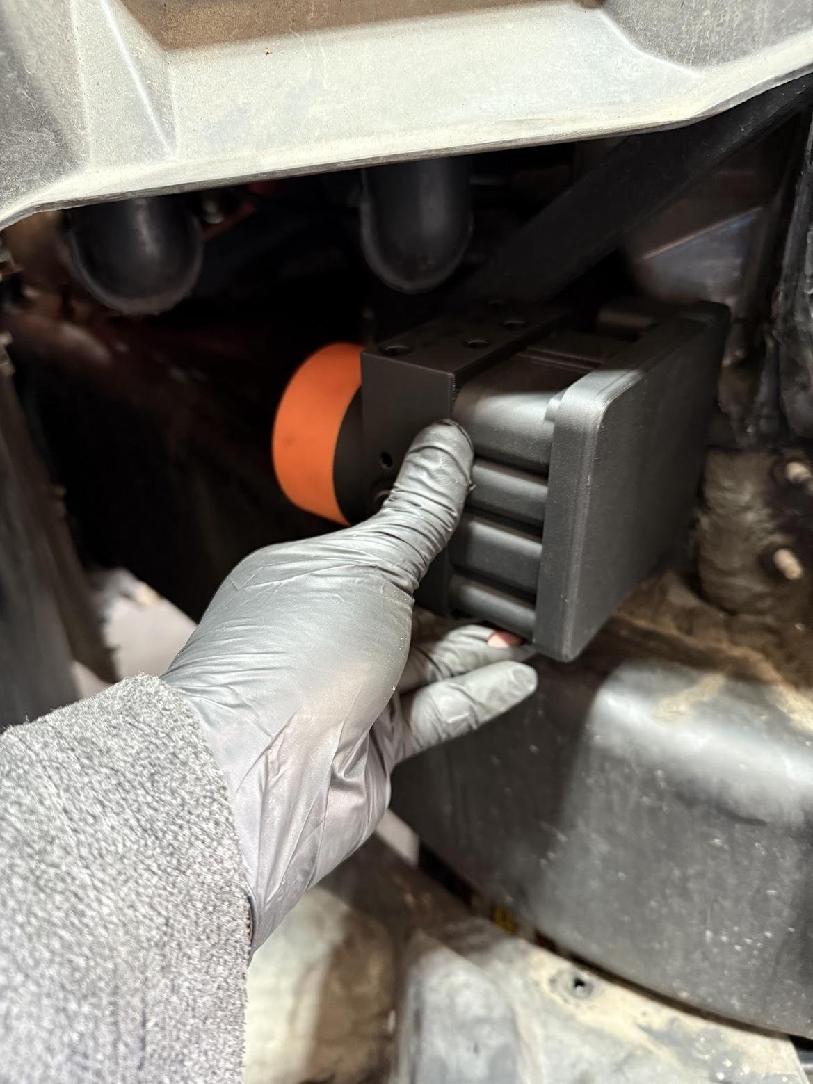
This weekend the intent was to get the ABS mounted, but I ran into a couple issues. The isolation mounts I got had way too long of studs and I wasted a ton of time trying to get them cut down only to destroy a few with heat and then find out they are uncomfortably soft mounts. I went and ordered replacements that are like 4x as expensive from McMaster, but have successfully been used before. Unfortunately this derailed my plans as I want the ABS in its final location before I attempt to start bending brake lines.
https://www.mcmaster.com/4403K84/
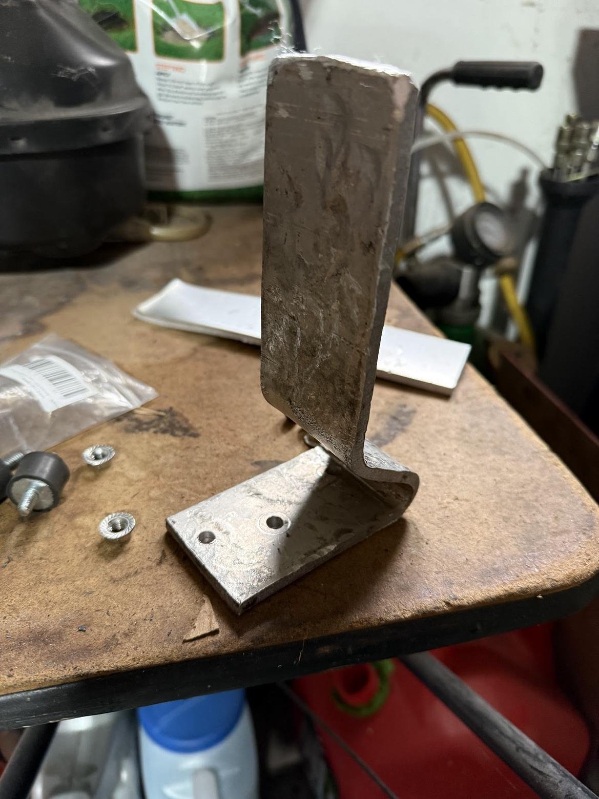
I forged a bracket out of 1/4″ aluminum. FYI if you need to bend aluminum, draw with a sharpie on both sides. Heat it with a torch until the sharpie disappears on both sides. Let it cool and it will be soft enough to bend. I snapped the first try done cold. It probably would have been smarter to just get some thinner steel to bend. I thought I was being smart and the aluminum would be easy. The intent is to put some rivnuts into the frame and bolt the bracket to it. That way I have a way to get the ABS off for service. I really wish I had a welder for this however. Side note- what home depot is charging for a couple short metric bolts is criminal. Order an assortment off amazon ahead of time.
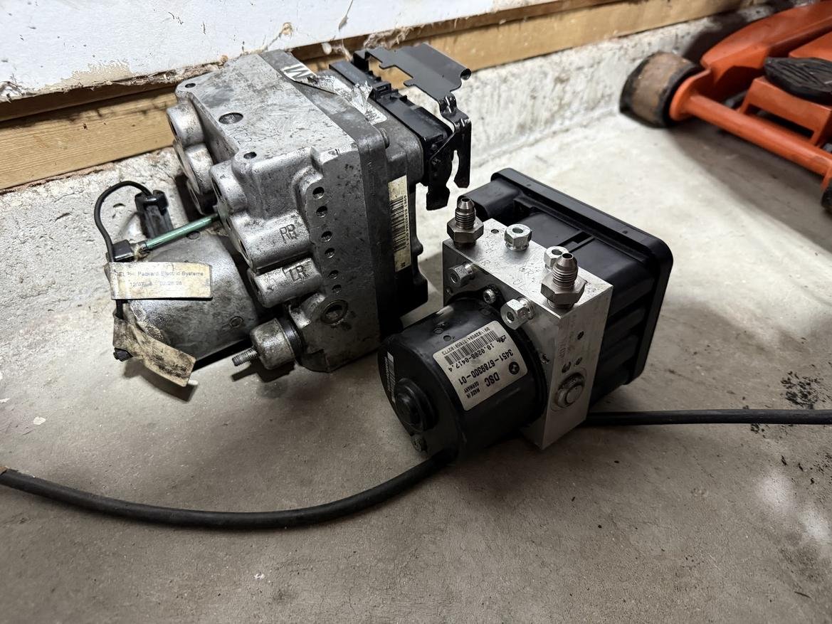
Even though I couldn’t progress with my bending, I did finish up the demolition. I got the old ABS out of the front of the car. It is HUGE compared to the mk60e1. It’s going to be nice having all the extra room at the front of the engine. It’ll make servicing the steering rack only moderately annoying as opposed to a day of swearing.
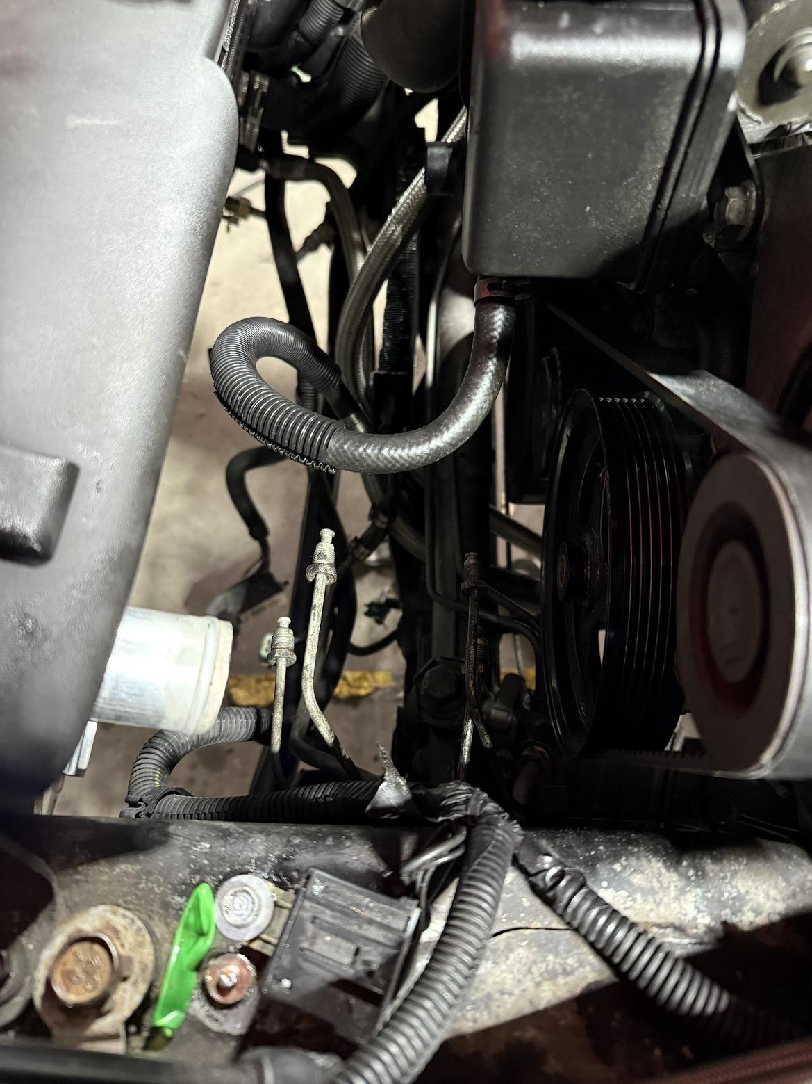
I also started running the harness for the wheel sensors. I didn’t expect a full replacement. I assumed it would just tie into the existing harness somewhere. I have to wonder If I can’t thin down the harness for the old ABS unit now. Running the wiring up and over the shroud instead of under it would be helpful as well. It won’t be as pretty, but it should be a lot more servicable than the current setup when it comes time to remove the fans.